 | Info
Sheets |
| | | | | | | | | | | | | | | | | | | | | | | | |
 | Out-
side |
| | | | |
|
| | | | |
Result : Searchterm 'Contrast Enhanced FAST' found in 3 terms [ ] and 2 definitions [ ] and 2 definitions [ ], (+ 14 Boolean[ ], (+ 14 Boolean[ ] results ] results
| | previous 6 - 10 (of 19) nextResult Pages : [1] [2 3 4] |  | | | | |  |
| |
|
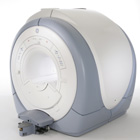
From GE Healthcare;
The Signa HDx MRI system is GE's leading edge whole body magnetic resonance scanner designed to support high resolution, high signal to noise ratio, and short scan times.
Signa HDx 3.0T offers new technologies like ultra- fast image reconstruction through the new XVRE recon engine, advancements in parallel imaging algorithms and the broadest range of premium applications. The HD applications, PROPELLER (high-quality brain imaging extremely resistant to motion artifacts), TRICKS ( contrast- enhanced angiographic vascular lower leg imaging), VIBRANT (for breast MRI), LAVA (high resolution liver imaging with shorter breath holds and better organ coverage) and MR Echo (high-definition cardiac images in real time) offer unique capabilities.
Device Information and Specification CLINICAL APPLICATION Whole body
CONFIGURATION Compact short bore SE, IR, 2D/3D GRE, RF-spoiled GRE, 2DFGRE, 2DFSPGR, 3DFGRE, 3DFSPGR, 3DTOFGRE, 3DFSPGR, 2DFSE, 2DFSE-XL, 2DFSE-IR, T1-FLAIR, SSFSE, EPI, DW-EPI, BRAVO, Angiography: 2D/3D TOF, 2D/3D phase contrast vascular IMAGING MODES Single, multislice, volume study, fast scan, multi slab, cine, localizer H*W*D 240 x 2216,6 x 201,6 cm POWER REQUIREMENTS 480 or 380/415, 3 phase ||
COOLING SYSTEM TYPE Closed-loop water-cooled grad. | | | | | |
| | | | | |
| |
|
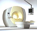
From Philips Medical Systems;
the Intera-family offers with this member a wide range of possibilities, efficiency and a ergonomic and intuitive serving-platform. Also available as Intera CV for cardiac and Intera I/T for interventional MR procedures.
The scanners are also equipped with SENSE technology, which is essential for high-quality contrast enhanced magnetic resonance angiography, interactive cardiac MR and diffusion tensor imaging ( DTI) fiber tracking.
The increased accuracy and clarity of MR scans obtained with this technology allow for faster and more accurate diagnosis of potential problems like patient friendliness and expands the breadth of applications including cardiology, oncology and interventional MR.
Device Information and Specification
CLINICAL APPLICATION
Whole body
CONFIGURATION
Short bore compact
Standard: head, body, C1, C3; Optional: Small joint, flex-E, flex-R, endocavitary (L and S), dual TMJ, knee, neck, T/L spine, breast; Optional phased array: Spine, pediatric, 3rd party connector; Optional SENSE coils: Flex-S-M-L, flex body, flex cardiac
SE, Modified-SE ( TSE), IR (T1, T2, PD), STIR, FLAIR, SPIR, FFE, T1-FFE, T2-FFE, Balanced FFE, TFE, Balanced TFE, Dynamic, Keyhole, 3D, Multi Chunk 3D, Multi Stack 3D, K Space Shutter, MTC, TSE, Dual IR, DRIVE, EPI, Cine, 2DMSS, DAVE, Mixed Mode; Angiography: PCA, MCA, Inflow MRA, CE
TR
2.9 (Omni), 1.6 (Power), 1.6 (Master/Expl) msec
TE
1.0 (Omni), 0.7 (Power), 0.5 (Master/Expl) msec
RapidView Recon. greater than 500 @ 256 Matrix
0.1 mm(Omni), 0.05 mm (Pwr/Mstr/Expl)
128 x 128, 256 x 256,512 x 512,1024 x 1024 (64 for BOLD img.)
Variable in 1% increments
Lum.: 120 cd/m2; contrast: 150:1
Variable (op. param. depend.)
POWER REQUIREMENTS
380/400 V
| | | |
• View the DATABASE results for 'Intera 1.5T™' (2).
| | | | |
| | | | | |
| |
|
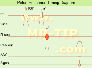
In simple ultra fast GRE imaging, TR and TE are so short, that tissues have a poor imaging signal and - more importantly - poor contrast except when contrast media enhanced ( contrast enhanced angiography). Therefore, the magnetization is 'prepared' during the preparation module, most frequently by an initial 180° inversion pulse.
In the pulse sequence timing diagram, the basic ultra fast gradient echo sequence is illustrated. The 180° inversion pulse is executed one time (to the left of the vertical line), the right side represents the data collection period and is often repeated depending on the acquisition parameters.
See also Pulse Sequence Timing Diagram, there you will find a description of the components.
Ultra fast GRE sequences have a short TR,TE, a low flip angle and TR is so short that image acquisition lasts less than 1 second and typically less than 500 ms. Common TR: 3-5 msec, TE: 2 msec, and the flip angle is about 5°.
Such sequences are often labeled with the prefix 'Turbo' like TurboFLASH, TurboFFE and TurboGRASS.
This allows one to center the subsequent ultra fast GRE data acquisition around the inversion time TI, where one of the tissues of interest has very little signal as its z-magnetization is passing through zero.
Unlike a standard inversion recovery (IR) sequence, all lines or a substantial segment of k-space image lines are acquired after a single inversion pulse, which can then together be considered as readout module. The readout module may use a variable flip angle approach, or the data acquisition may be divided into multiple segments (shots). The latter is useful particularly in cardiac imaging where acquiring all lines in a single segment may take too long relative to the cardiac cycle to provide adequate temporal resolution.
If multiple lines are acquired after a single pulse, the pulse sequence is a type of gradient echo echo planar imaging (EPI) pulse sequence. See also Magnetization Prepared Rapid Gradient Echo ( MPRAGE) and Turbo Field Echo ( TFE). | | | |
• View the DATABASE results for 'Ultrafast Gradient Echo Sequence' (13).
| | | | |
| | | | | |
| |
|
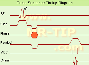
(GRE - sequence) A gradient echo is generated by using a pair of bipolar gradient pulses. In the pulse sequence timing diagram, the basic gradient echo sequence is illustrated. There is no refocusing 180° pulse and the data are sampled during a gradient echo, which is achieved by dephasing the spins with a negatively pulsed gradient before they are rephased by an opposite gradient with opposite polarity to generate the echo.
See also the Pulse Sequence Timing Diagram. There you will find a description of the components.
The excitation pulse is termed the alpha pulse α. It tilts the magnetization by a flip angle α, which is typically between 0° and 90°. With a small flip angle there is a reduction in the value of transverse magnetization that will affect subsequent RF pulses.
The flip angle can also be slowly increased during data acquisition (variable flip angle: tilt optimized nonsaturation excitation).
The data are not acquired in a steady state, where z-magnetization recovery and destruction by ad-pulses are balanced.
However, the z-magnetization is used up by tilting a little more of the remaining z-magnetization into the xy-plane for each acquired imaging line.
Gradient echo imaging is typically accomplished by examining the FID, whereas the read gradient is turned on for localization of the signal in the readout direction. T2* is the characteristic decay time constant associated with the FID. The contrast and signal generated by a gradient echo depend on the size of the longitudinal magnetization and the flip angle.
When α = 90° the sequence is identical to the so-called partial saturation or saturation recovery pulse sequence.
In standard GRE imaging, this basic pulse sequence is repeated as many times as image lines have to be acquired.
Additional gradients or radio frequency pulses are introduced with the aim to spoil to refocus the xy-magnetization at the moment when the spin system is subject to the next α pulse.
As a result of the short repetition time, the z-magnetization cannot fully recover and after a few initial α pulses there is an equilibrium established between z-magnetization recovery and z-magnetization reduction due to the α pulses.
Gradient echoes have a lower SAR, are more sensitive to field inhomogeneities and have a reduced crosstalk, so that a small or no slice gap can be used.
In or out of phase imaging depending on the selected TE (and field strength of the magnet) is possible.
As the flip angle is decreased, T1 weighting can be maintained by reducing the TR.
T2* weighting can be minimized by keeping the TE as short as possible, but pure T2 weighting is not possible.
By using a reduced flip angle, some of the magnetization value remains longitudinal (less time needed to achieve full recovery) and for a certain T1 and TR, there exist one flip angle that will give the most signal, known as the "Ernst angle".
Contrast values:
PD weighted: Small flip angle (no T1), long TR (no T1) and short TE (no T2*)
T1 weighted: Large flip angle (70°), short TR (less than 50ms) and short TE
T2* weighted: Small flip angle, some longer TR (100 ms) and long TE (20 ms)
Classification of GRE sequences can be made into four categories:
See also Gradient Recalled Echo Sequence, Spoiled Gradient Echo Sequence, Refocused Gradient Echo Sequence, Ultrafast Gradient Echo Sequence.
| | | | | |
• View the DATABASE results for 'Gradient Echo Sequence' (70).
| | | | |  Further Reading: Further Reading: | | Basics:
|
|
News & More:
| |
| |
| | | | | |
| |
|
Flow phenomena are intrinsic processes in the human body. Organs like the heart, the brain or the kidneys need large amounts of blood and the blood flow varies depending on their degree of activity. Magnetic resonance imaging has a high sensitivity to flow and offers accurate, reproducible, and noninvasive methods for the quantification of flow. MRI flow measurements yield information of blood supply of of various vessels and tissues as well as cerebro spinal fluid movement.
Flow can be measured and visualized with different pulse sequences (e.g. phase contrast sequence, cine sequence, time of flight angiography) or contrast enhanced MRI methods (e.g. perfusion imaging, arterial spin labeling).
The blood volume per time (flow) is measured in: cm3/s or ml/min. The blood flow-velocity decreases gradually dependent on the vessel diameter, from approximately 50 cm per second in arteries with a diameter of around 6 mm like the carotids, to 0.3 cm per second in the small arterioles.
Different flow types in human body:
•
Behaves like stationary tissue, the signal intensity depends on T1, T2 and PD = Stagnant flow
•
Flow with consistent velocities across a vessel = Laminar flow
•
Laminar flow passes through a stricture or stenosis (in the center fast flow, near the walls the flow spirals) = Vortex flow
•
Flow at different velocities that fluctuates = Turbulent flow
See also Flow Effects, Flow Artifact, Flow Quantification, Flow Related Enhancement, Flow Encoding, Flow Void, Cerebro Spinal Fluid Pulsation Artifact, Cardiovascular Imaging and Cardiac MRI. | | | | | |
• View the DATABASE results for 'Flow' (113).
| | |
• View the NEWS results for 'Flow' (7).
| | | | | | Further Reading: | News & More:
|
|
| |
| | | | |
| | |
| | | |
|
| |
 | Look
Ups |
| |


